

Ball balancing system with PID control
2022 / Matías Bergerman, Philippe Dutriez, Francisco Ledesma, Xi Lin, Pablo Smolkin
This project was made for the course 22.85 - Control Systems, at the Buenos Aires Institute of Technology (ITBA).
Professor: Ing. Víctor Nasini.
Introduction 🔗
For the final project of the Control Systems course, we decided to make a ball balancing system implemented with PID (proportional–integral–derivative) control. The goal of the device is to balance a ball on a flat platform by adjusting its angle with respect to two orthogonal axes.
The position of the ball is determined with the use of a digital camera which is located over the platform, and a Raspberry Pi that processes the image output. Given the measured and desired ball position, the appropiate tilt of the platform is calculated and achieved with the use of two servo motors which adjust its angle independently over both orthogonal axes. Furthermore, the Raspberry PI is connected wirelessly to an MQTT server such that it can continously transmit real-time data regarding the measured and desired ball position. This information can be analyzed from any terminal connected to the same server, and plotted in real-time using a Python program.
Hardware 🔗
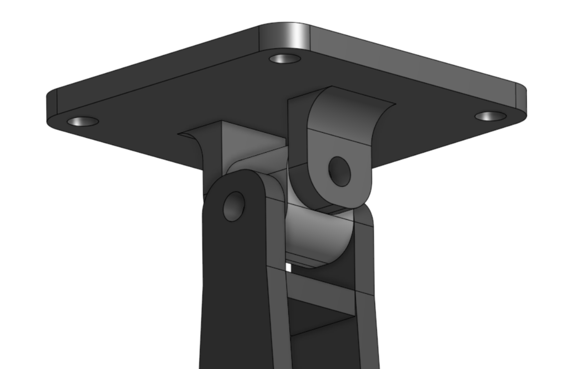
To build the project we used a 25cm x 25cm wooden platform which was supported by a 3D-printed universal joint:
A Logitech C920 HD PRO camera was used for measuring the ball position, which was connected over USB to the Raspberry Pi. An L-shaped PVC tube was used to support the camera over the device such that it is centered and at an appropiate distance from the platform.
To control the platform incline, two MG90S servo motors were used which were attached to the platform via rigid metal wire used to transfer the motors movement.
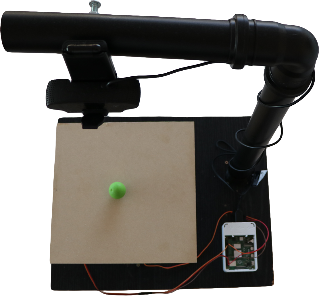
A Raspberry Pi 4B was used for controlling the servo motors and acquiring and processing the camera image data.
Software 🔗
Ball detection 🔗
To determine the ball position, the acquired camera images are analyzed by a Python program using OpenCV. To achieve this, a popular example code was adapted which detects circular objets of the designated color on any image.
The steps in the algorithm are as follows:
- Downsize the image resolution in order to speed up processing time.
- Apply a gaussian blur to the image.
- Apply a color space transformation to the image from RGB to HSV.
- Apply a binary mask which preserves only the pixels for which its HSV color values are within the designated range, corresponding to the ball color.
- Apply a series of “erosions” and “dilations” in order to remove any small blob that may have remained.
- Find the largest remaining contour in the image.
- Calculate the centroid of the circle enclosing the contour.
Motor control 🔗
The servo motors used have power terminals which are independent from the data signal. For this reason, they can be controlled from the Raspberry Pi without the need for additional hardware.
In order for each motor to position at the desired angle, a PWM signal must be provided with an appropiate duty-cycle. The Raspberry Pi has hardware PWM controllers which were employed for this task.
PID 🔗
For the implementation of the PID control, the following simple instructions were implemented:
dt = time() - previous_time
previous_time = time()

P = error
I = I + (error * dt)
D = (error - previous_error) / dt

output = (Kp * P) + (Ki * I) + (Kd * D)
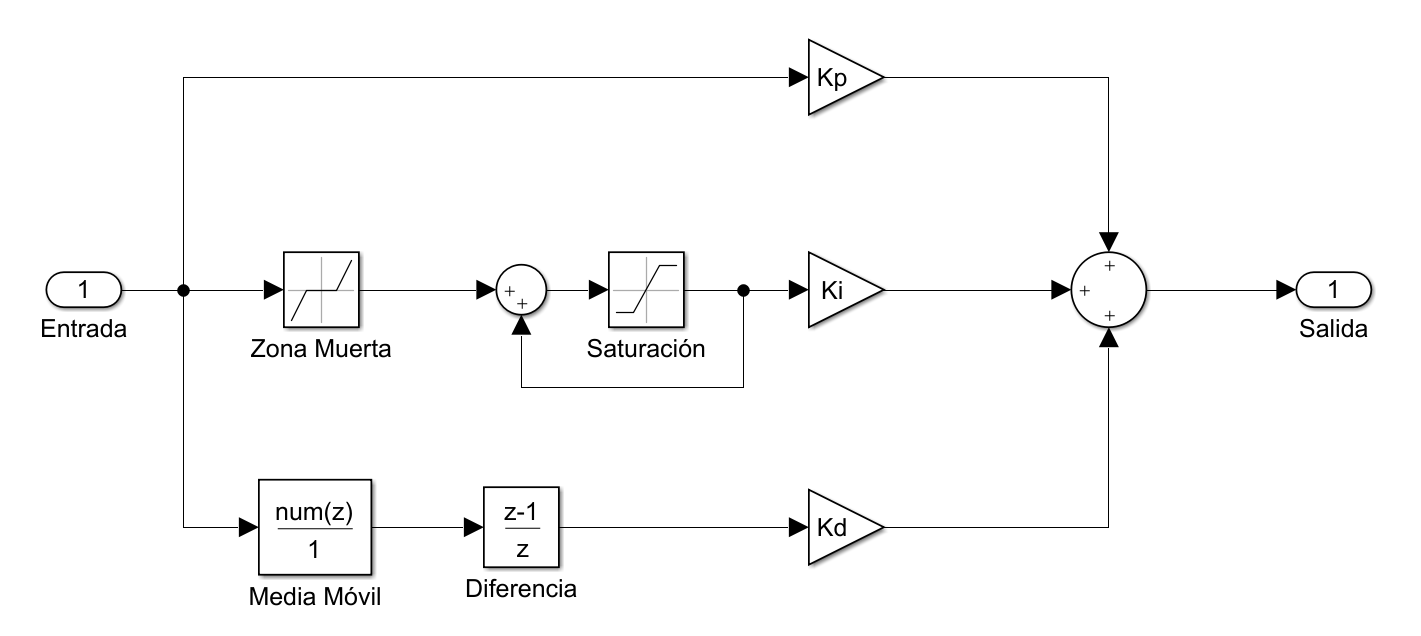
However, certain issues arose from this implementation which needed to be addressed. The main problem is that the ball measurement carries significant noise, mainly due to the device vibration, the camera precision, the systems variable latency, and the detection algorithms slight inconsistencies. This high frequency noise is further amplified by the derivative component of the controller, consecuently the signal sent to the motors contains noise and the whole platform vibrates notably. This issue was resolved by placing a low-pass filter only at the input of the derivative block, in order to reduce the high frequency noise amplitude which this block recieves. To simplify the implementation, a moving average filter with 5 taps was implemented.
Another issue found was the integrative component windup. The acummulated error value could increse further that what was reasonable, so it had to be saturated. This is because if for any reason the ball remains far from the set-point for a long time, the integral should not grow arbitrarily preventing the stabilization of the ball when it becomes free to move.
Finally, the system was found to have a “dead-zone”. This is, if the ball is not moving then it requires a minimum inclination angle in order to start its movement. Because of this, small errors are accumulated in the integral and after some time the ball is flung across when the platforms angle reaches the minimum threshold for the ball to move. To mitigate this problem, a “dead-zone” was applied to the input value of the integrative block, such that it ignores very small error values.
The resulting diagram is as follows:
Real-time data transmission 🔗
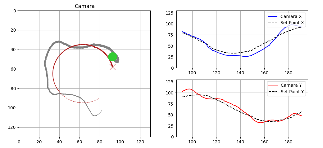
In order to transmit data in real time a client was implemented on the Raspberry Pi which connects via the MQTT protocol, commonly used in IoT applications. This way, information is sent to an external server and becomes accessible to any other MQTT client connected to the same server. This data is received thorugh a terminal and plotted in real time using Python. On the next figure, a screen capture of the application developed for this purpose is shown. On the left, the current ball position is displayed as registered by the camera over the platform using a green circle, and the desired position is shown with a cross. Moreover, the previous path of the ball is represented by a gray trail. On the right, the same information for each axis is displayed on independent plots and with regards to time. In this example, the ball is attempting to follow a circular path, this is represented by a sinusoidal waveform for each axis.
Project code 🔗
The code was implemented using Python with the multiprocessing library to allow for concurrent execution of the different system modules, which communicate between each other using Pipes. The files are available for download:
Additionally, a program was used to calibrate the HSV thresholds for the binary mask used in the ball detection process:
For the plotter, the mosquitto MQTT broker was used, and the following application was implemented: